| Availability: | |
|---|---|
| Quantity: | |

2FRM16-3X/160LB
Rexroth
R900424902
For subplate mounting
Porting pattern according to DIN 24340 form G and ISO 6263
Mechanical actuation
Pressure compensator stroke limitation, optional
Start-up jump reduction
Flow control in both directions through rectifier sandwich plate
For subplate mounting
Porting pattern according to DIN 24340 form G and ISO 6263
Mechanical actuation
Pressure compensator stroke limitation, optional
Start-up jump reduction
Flow control in both directions through rectifier sandwich plate
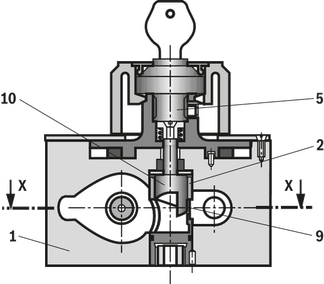
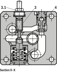
Flow control valves type 2FRM are 2-way flow control valves. They are used to maintain a constant flow, mostly independent of pressure and temperature.
Generally, the valves consist of housing (1), orifice bush (2), pressure compensator (3) with optional stroke limitation (3.1), check valve (4), adjustment element (5) at type 2FRM as well as geared piston drive (6), and directional valve (7). The flow from channel A to channel B is throttled at the throttling point (9). The throttle cross-section of type 2FRM is set by mechanically turning the curved bolt (10) over the adjustment element (5). The positioning velocity can be set by means of the throttle check valve (6.3 and 6.4). To fix the required adjustment range, the geared piston drive (6) is equipped with an adjustable stroke limitation (6.1 and 6.2) on both sides. An upstream pressure compensator (3) is included to ensure a pressure-independent and constant flow at throttling point (9).
Temperature independence is achieved thanks to the orifice design of the throttling point.
The free return flow from channel B to channel A is directed via the check valve (4).
The regulated flow only flows from channel A to B.
For oscillating flows (forward and return flow), a rectifier sandwich plate type Z4S can be installed under the flow control valve.
01 | 02 | 03 | 04 | 05 | 06 | 07 | 08 | 09 | 10 | 11 | ||
2FR | – | 3X | / | * |
01 | 2-way flow control valve | 2FR |
Type of actuation | ||
02 | Mechanical | M |
Hydraulic | H | |
Electro-hydraulic | W | |
03 | Size 10 | 10 |
Size 16 | 16 | |
04 | Component series 30 ... 39 (30 ... 39: unchanged installation and connection dimensions) | 3X |
Flow range A to B | ||
05 | Size 10, linear | |
Up to 10 l/min | 10L | |
Up to 16 l/min | 16L | |
Up to 25 l/min | 25L | |
Up to 50 l/min | 50L | |
Size 16, linear | ||
Up to 60 l/min | 60L | |
Up to 100 l/min | 100L | |
Up to 160 l/min | 160L | |
06 | Without pressure compensator stroke limitation | no code |
With pressure compensator stroke limitation | B | |
07 | Without actual value potentiometer | no code |
With actual value potentiometer (only types 2FRH and 2FRW) | P | |
08 | With concealed manual override (standard) | N9 |
With manual override | N | |
Without manual override | no code | |
Electrical connection | ||
09 | Individual connection | |
Without mating connector; connector DIN EN 175301-803 | K4 1) | |
Seal material | ||
10 | NBR seals | no code |
FKM seals | V | |
Observe compatibility of seals with hydraulic fluid used. | ||
11 | Further details in the plain text | * |
1) Mating connectors, separate order.
Preferred types and standard units are contained in the EPS (standard price list).
Size | 10 | 16 | ||
Weight | kg | 5.6 | 11.3 | |
Installation position | any | |||
Ambient temperature range | NBR seals | °C | -30 … +80 | |
FKM seals | °C | -20 … +80 | ||
Size | 10 | 16 | |||||||
Maximum flow | l/min | 10 16 25 50 | 60 100 160 | ||||||
Maximum operating pressure | Anschluss A | bar | 315 | ||||||
Pressure differential with free return flow B to A, qV-dependent | bar | 2 | 2.5 | 3.5 | 6 | 2.8 | 4.3 | 7.3 | |
Minimum pressure differential | bar | 3 … 7 | 5 … 12 | ||||||
Flow control | Thermally stable (qV max) at –20 … +80 °C | % | ± 2 | ||||||
Pressure stable (qV max) to Δp = 315 bar | % | ± 2 | < ± 5 | ||||||
Hydraulic fluid | see table | ||||||||
Hydraulic fluid temperature range | NBR seals | °C | -30 … +80 | ||||||
FKM seals | °C | -20 … +80 | |||||||
Viscosity range | mm²/s | 10 … 800 | |||||||
Maximum admissible degree of contamination of the hydraulic fluid 1) | Class 20/18/15 according to ISO 4406 (c) | ||||||||
| 1) | The cleanliness classes specified for the components must be adhered to in hydraulic systems. Effective filtration prevents faults and simultaneously increases the life cycle of the components. For the selection of the filters, see www.boschrexroth.com/filter. |
Hydraulic fluid | Classification | Suitable sealing materials | Standards | |
Mineral oils | HL, HLP | NBR, FKM | DIN 51524 | |
Bio-degradable | Insoluble in water | HETG | NBR, FKM | VDMA 24568 |
HEES | FKM | |||
Soluble in water | HEPG | FKM | VDMA 24568 | |
Containing water | Water-free | HFDU | FKM | ISO 12922 |
Containing water | HFC (Fuchs Hydrotherm 46M, Petrofer Ultra Safe 620) | NBR | ISO 12922 | |
Important information on hydraulic fluids! For further information and data on the use of other hydraulic fluids, please refer to data sheet 90220 or contact us! There may be limitations regarding the technical valve data (temperature, pressure range, life cycle, maintenance intervals, etc.)! The flash point of the hydraulic fluid used must be 40 K higher than the maximum solenoid surface temperature. Flame-resistant – containing water: Maximum pressure differential per control edge 50 bar. Pressure pre-loading at the tank port >20% of the pressure differential; otherwise, increased cavitation Life cycle compared to operation with mineral oil HL, HLP 50 to 100 % Bio-degradable: When using bio-degradable hydraulic fluids that are zinc-solving, zinc may accumulate in the fluid (700 mg zinc per pole tube) | ||||
Resistance | Ω | 1000 |
Load capacity | W | 5 |
Maximum wiper current | A | 0.12 |
Protection class according to EN 60529 | IP65 | |
Control limit error at 10°/s (depending on the positioning velocity) | ° | ± 1.5 |
Dimensions in mm

NG | B1 | B2 | B3 | B4 | B5 | B6 | ØD1 | ØD2 | D3 | H1 | H2 | H3 | H4 | H5 | L1 | L2 | L3 | L4 | T1 |
mm | mm | mm | mm | mm | mm | mm | mm | mm | mm | mm | mm | mm | mm | mm | mm | mm | mm | mm | |
| 10 | 101.5 | 82.5 | 9.5 | 68 | 58.7 | 35.5 | 9 | 15 | 6 | 125 | 95 | 26 | 51 | 60 | 95 | 76 | 9.5 | 79.4 | 13 |
| 16 | 123.5 | 101.5 | 11 | 81.5 | 72.5 | 41.5 | 11 | 18 | 6 | 147 | 117 | 34 | 72 | 82 | 123.5 | 101.5 | 11 | 102.4 | 12 |
Subplates (separate order)
Size 10:
G 279/01 (G 1/2)
G 280/01 (G 3/4)
Size 16:
G 281/01 (G 1)
G 282/01 (G 1 1/4)
Valve mounting screws (separate order)
Size 10:
4 hexagon socket head cap screws ISO 4762 - M8 x 50 - 10.9-flZn-240h-L
(friction coefficient μtotal = 0.09 to 0.14);
Tightening torque MA = 30 Nm ± 10 %,
Material no. R913000543
Size 16:
4 hexagon socket head cap screws ISO 4762 - M10 x 80 - 10.9-flZn-240h-L
(friction coefficient μtotal = 0.09 to 0.14);
Tightening torque MA = 64 Nm ±10 %,
Material no. R913000496
Dimensions in mm
NG | B1 | B2 | B3 | B4 | B5 | B6 | ØD1 | ØD2 | D3 | H1 | H2 | H3 | H4 | H5 | L1 | L2 | L3 | L4 | T1 |
mm | mm | mm | mm | mm | mm | mm | mm | mm | mm | mm | mm | mm | mm | mm | mm | mm | mm | mm | |
| 10 | 101.5 | 82.5 | 9.5 | 68 | 58.7 | 35.5 | 9 | 15 | 6 | 125 | 95 | 26 | 51 | 60 | 95 | 76 | 9.5 | 79.4 | 13 |
| 16 | 123.5 | 101.5 | 11 | 81.5 | 72.5 | 41.5 | 11 | 18 | 6 | 147 | 117 | 34 | 72 | 82 | 123.5 | 101.5 | 11 | 102.4 | 12 |
Subplates (separate order)
Size 10:
G 279/01 (G 1/2)
G 280/01 (G 3/4)
Size 16:
G 281/01 (G 1)
G 282/01 (G 1 1/4)
Valve mounting screws (separate order)
Size 10:
4 hexagon socket head cap screws ISO 4762 - M8 x 50 - 10.9-flZn-240h-L
(friction coefficient μtotal = 0.09 to 0.14);
Tightening torque MA = 30 Nm ± 10 %,
Material no. R913000543
Size 16:
4 hexagon socket head cap screws ISO 4762 - M10 x 80 - 10.9-flZn-240h-L
(friction coefficient μtotal = 0.09 to 0.14);
Tightening torque MA = 64 Nm ±10 %,
Material no. R913000496


